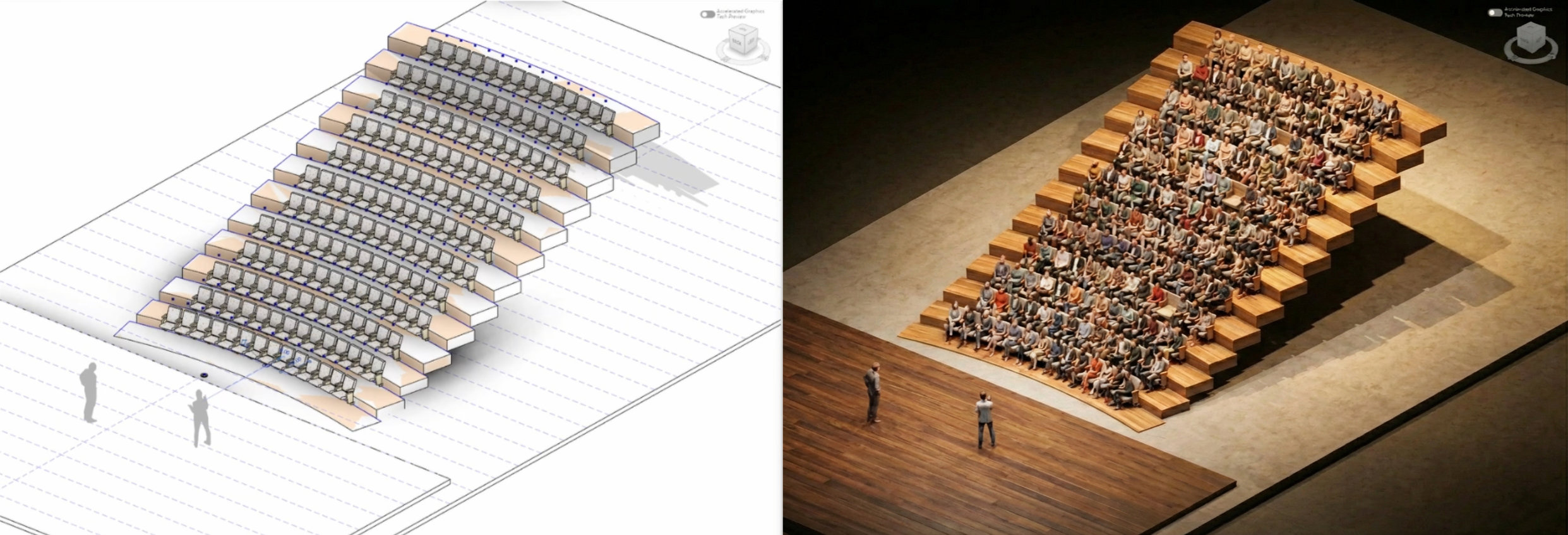
We have all likely experienced a situation in a cinema or theater where our enjoyment of the performance was drastically reduced by the head of the person sitting in the row in front blocking our view. From the user’s perspective, this is an ergonomic defect. From the perspective of the engineer designing the auditorium space, this is not an accident, but the result of a calculation error in the audience elevation profile, defined by the C-Value parameter (sightline clearance).
In the traditional design process, coordinating floor geometry with visibility requirements is iterative, time-consuming, and prone to error with every change in seating layout. In this case study, we analyze how utilizing Computational Design within the Revit environment allows for the automation of this issue, combining mathematical precision with native BIM geometry.
The Challenge: Breaking the Static Workflow Standard approaches to modeling grandstands in Revit often rely on manually defining floors or using static families to which equipment is secondarily fitted. This creates operational bottlenecks during project revisions—changing the row spacing or the height of the Focal Point on stage forces a reconstruction of the entire section.
To eliminate this bottleneck, we developed a Dynamo script that reverses this dependency. The algorithm treats the target C-Value (typically 60–120 mm) as the primary form-generating parameter.
The Solution: Ray-Tracing & Native Geometry The script leverages ray-tracing logic, simulating the line of sight for each row. The system calculates the vector from the viewer’s eye to the point on the stage and then, accounting for the clearance margin over the predecessor’s head, determines the floor elevation for the subsequent tier.
As a result, instead of “dead” geometry, we obtain a parametric system that reacts to input variables in real-time. Crucially for model performance, the script generates native geometry (Solids/DirectShapes) rather than database-heavy meshes. By employing selection stabilization nodes (Element.GetLocation), the tool runs smoothly in Dynamo Player, allowing the designer to quickly iterate between straight and radial layouts.
Data Integrity & Idempotency As designers, we expect automation to not only speed up modeling but also ensure information integrity. Therefore, the developed system goes beyond geometry. The view-generating script is tightly integrated with the model—it automatically assigns unique identifiers (e.g., R5_S12) and writes them to the ‘Mark’ parameter in the chair families. This ensures full consistency between the 3D view name and the element in the equipment schedule.
Visual Verification: Overcoming API Limitations Generating correct geometry is only half the engineering success. Verifying assumptions requires checking the view from the perspective of a specific seat. Manually creating hundreds of cameras in Revit is operationally inefficient, so this process was also automated.
However, here we encounter specific limitations within the Revit API, which defaults to Imperial units and enforces specific behaviors for perspective views.
Unit Conversion: Direct coordinate conversion without unit translation often results in cameras being placed at the wrong scale, manifesting as distorted, “microscopic” views.
The Crop Box Issue: For a perspective to exist, the CropBoxActive property must be True.
To achieve a legible image simulating a natural field of view, we implemented a “Silent Crop” technique using Python. The algorithm not only correctly converts metric coordinates to Revit’s internal units but also dynamically scales the cropping frame based on the viewer’s distance from the stage, maintaining a cinematic 16:9 aspect ratio. This frame is then programmatically hidden (CropBoxVisible = False). Consequently, the user receives a clean, navigable view, free of annoying borders, ready for immediate assessment or rendering.
It is also worth highlighting the tool’s idempotency. Before creating a view, the algorithm checks the project database—if a view for a given seat already exists, the system skips it instead of generating duplicates. This approach protects model hygiene and conserves workstation computational resources.
This solution demonstrates how Computational Design is evolving from a tool for creating complex forms into an essential component of Quality Assurance and BIM process optimization in daily design practice.